SOLAR MOUNTING SYSTEMS
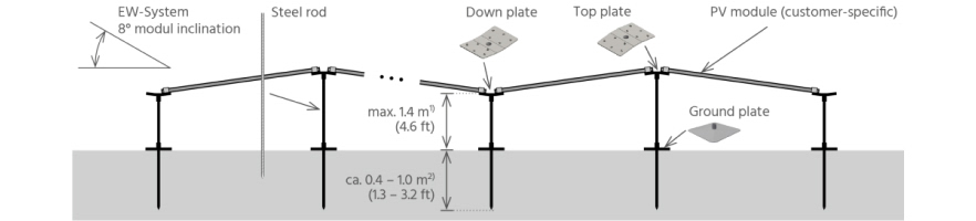
PEG® EW System Overview:
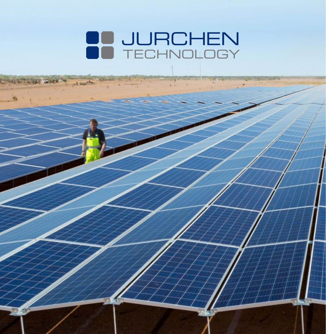
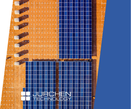
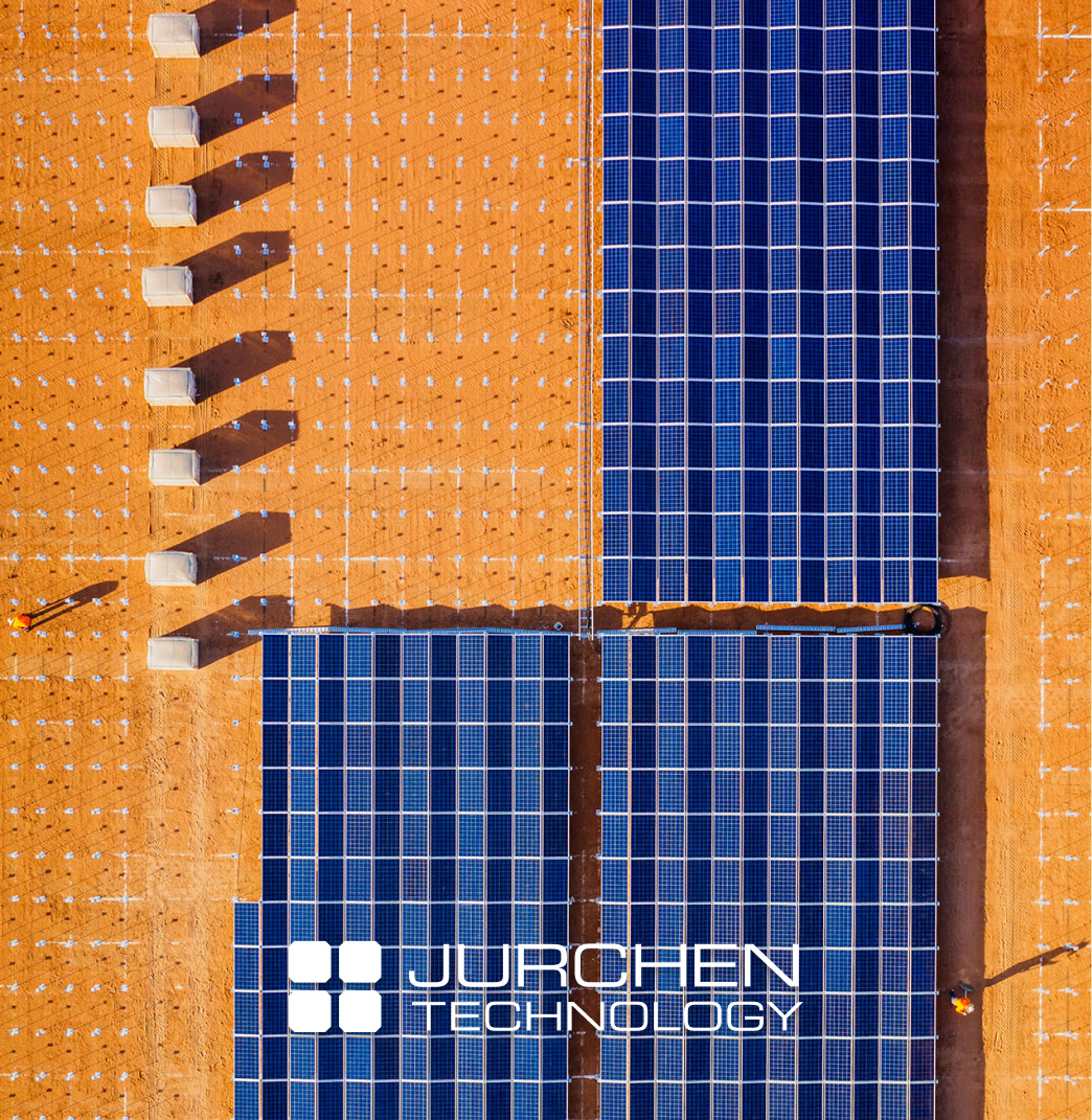
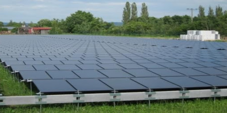
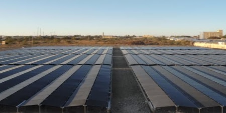
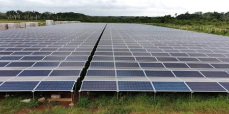
The PEG® provides a unique simplified high-density ground mount solution that produces 225% more land yield versus trackers and fixed tilt systems. The low profile 8-degree tilt design requires minimal spacing between modules creating an ocean of solar panels.
The PEG® is very mobile, light weight, simple to install with only hand tools, no DC trenching, no foundations, no concrete and requires minimal land giving you flexibility of choosing where to install. The PEG® provides a more sustainable solution for solar at a significantly reduced CAPEX.
- Extremely high land use. Comparison per acre:
- 3 times higher DC vs trackers, ~ twice higher vs fixed-tilt
- 225% higher yield vs trackers & other fixed-tilt systems
- Extremely cost-effective CAPEX (supply and installations)
- Low profile & shallow foundations, <1m (3.3ft) above & below ground
- Very light system, ~9 kg (~20lb) per kWp (540W modules)
- Proven globally, over 420MWp installed
- Patented design
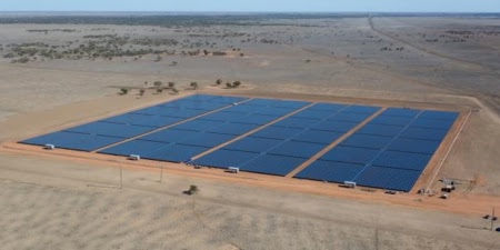
THE PEG® EW SYSTEM, THE MODULES COVERING ~95-98% OF THE DC AREA WITH NARROW GAPS BETWEEN THE BLOCKS
DESIGN CHARACTERISTICS
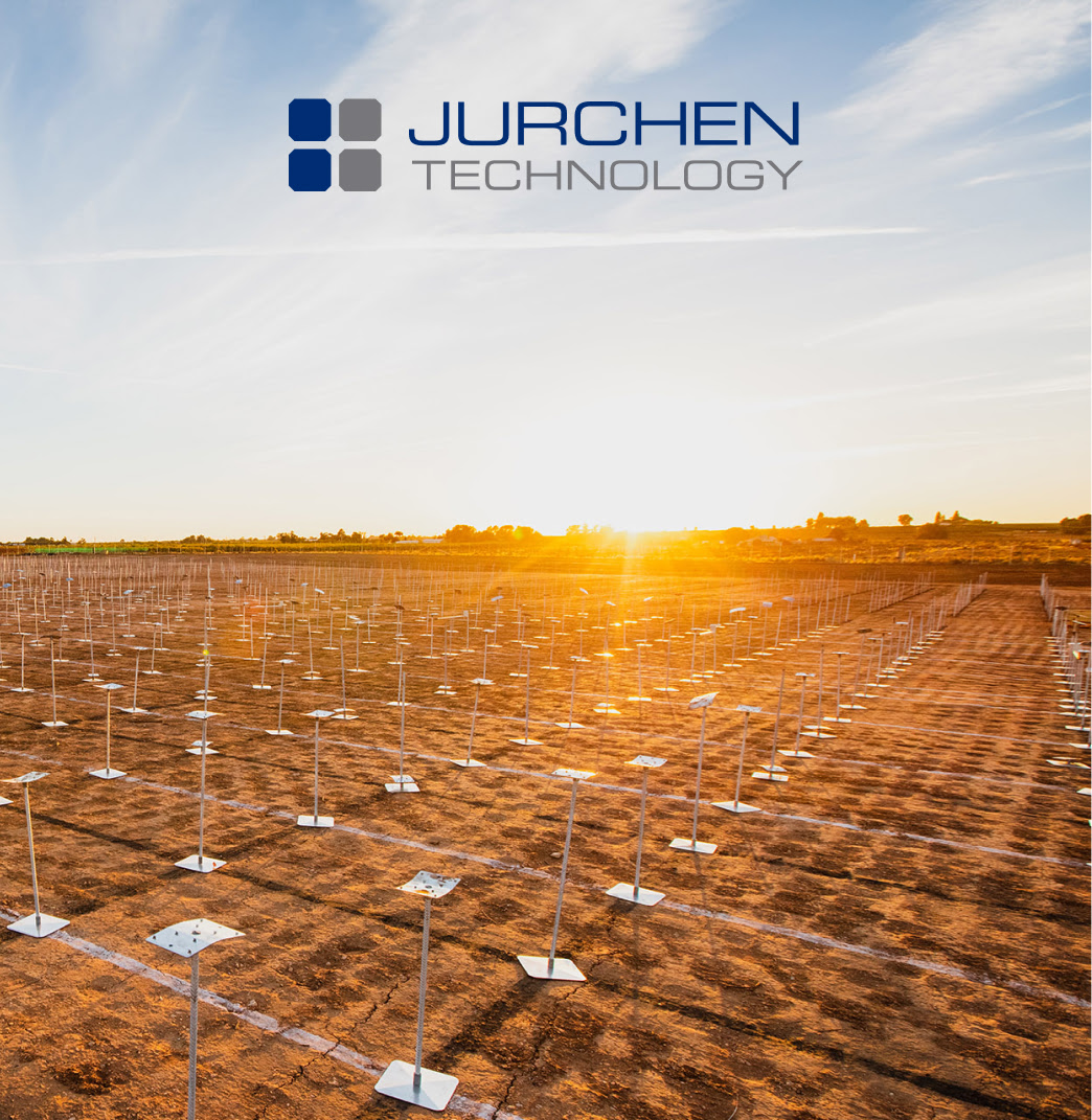
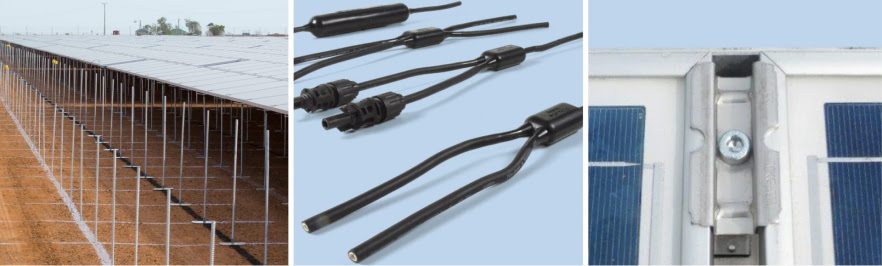
- Only 3 items: Steel rod, Ground plate and Top plate
- Modules at 8 deg E-W tilt, laid on the Top plates under the module’s corners
- Optional anchor rods for soft soil or need for shallow foundations
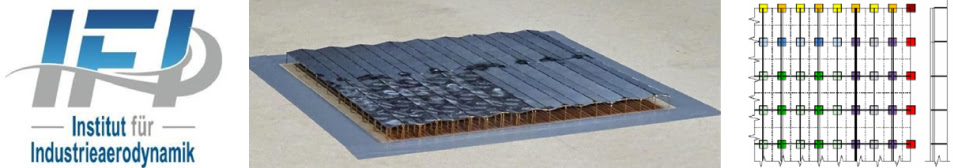
- Wind Tunnel tests successfully completedby IFI in Germany, in 2012 & 2020
- Max wind speed TBD per country, e.g.ASCII 7-10: ~185mph (~300km/hr) *
- Max snow load: ~50-60PSF (Pound perSquare Foot) *
* The wind and snow limits are subject tosite-specific calculated loads, determined mainly by the site wind speed, snowload and local code. The PEG® EW design might require additional support, subject to the max loads allowed by the module manufacturer and the mechanicalanalysis of the substructure.
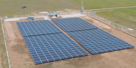
LAND USE
Extremely high land use:
- ~1.9MWp/Hectare
- (~0.8MWp/Acre)
- with ~550W modules
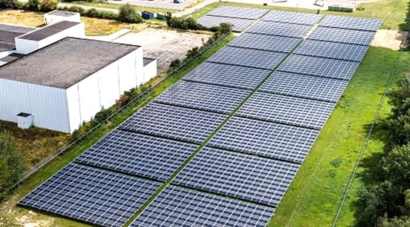
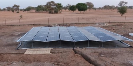
PEG® on a very narrow land, ~10m wide
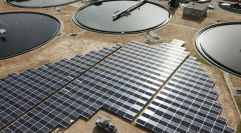
Non-rectangle PEG® block
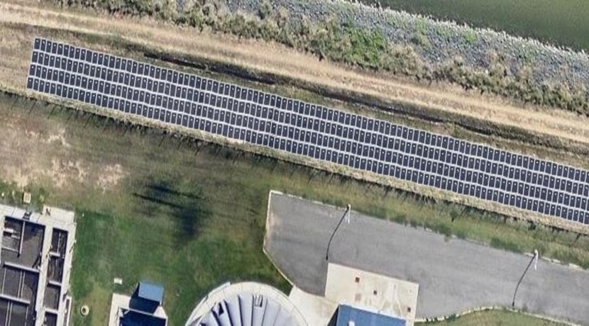
PEG® on a very narrow land, ~10m wide
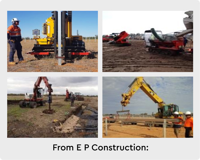
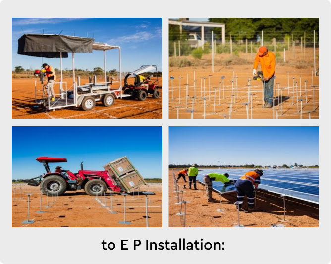
INSTALLATION METHODOLOGY
CONSTRUCTION PRACTICES ARE IRRELEVANT
- Low quantity of material and labor
- Without: Concrete, trenching and heavy machines
- Working height: ~1m (~3.5ft)
- Lightweight substructure, <3kg (7 lb) per item
PEG®: CAPEX COSTS SAVING VS OTHER SYSTEMS
| Cost Factor | Saving |
|---|---|
| Material | Substructure: ~50-65% less, DC cables: ~20-30% less |
| Logistics | ~50% less due to far lower substructure quantities and weight |
| Labor | ~50% less due to less labour time (hr/MW) & skilled labour (avg. hr cost) |
| Construction material |
No concrete & sand is required for foundations or DC trenching |
| Machinery & tools |
No heavy machinery is required (e.g. ramming, trenching, concreting). Only small forklift for site logistics and hand tools required. |
| Site operation | ~30-50% less installation time, leading to saving of site operation costs, e.g. management, safety & security labor & equipment, consumables, Etc. |
| Safety | Far simpler installation process, e.g. without working on heights and without heavy substructure items, leading to significant less OHS effort and injury risks |
| Land | DC area ~50-65% smaller a Lower land acquisition / rent costs, lower installation costs, shorter perimeter fence |
Worldwide Installations
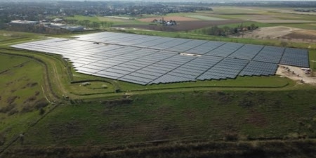
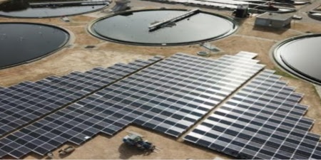
you can find information on the website:
contacts